Output
Devices
This
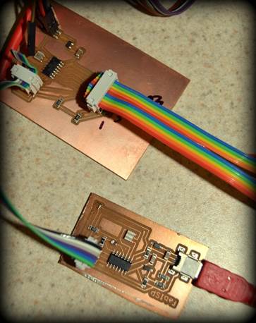
week our assignment was to add an output device to a microcontroller board
we’ve designed. Then we had to program the microcontroller. We used our FabISPs
we built earlier in the course again. I chose to use a LCD as my sensor. Our
instructor was against allowing us to do an RGB LED, as most of us used a
single color LED last week to go with our inputs.
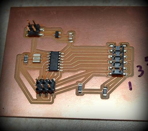
Eagle Cad is a lot easier to use now. Loading
the Eagle Fab libraries
is imperative to getting all the right components. It is useful to name your
traces for the routing process. Once again, the solder paste was applied using
a Silhouette cut vinyl stencil. Here is my schematic.
After my board was baked and cooled, I was ready to solder a cable to my LCD
screen. I used a Lumex S01602 D/A LCD.
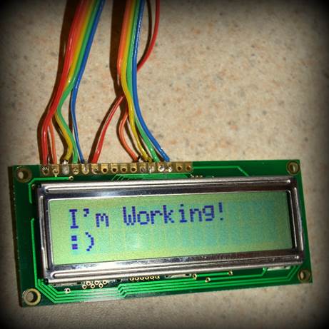
With this data sheet I
found to find out where to solder my wires to the LCD pins. Finding an example
Arduino code was simple; File> Examples>LiquidCrystal>HelloWorld. I
had a fun time changing the code to change the LCD screen. It was a satisfying
project overall. Here is my Arduino code.